Shopping Cart


TRAINING & EDUCATION SYSTEMS
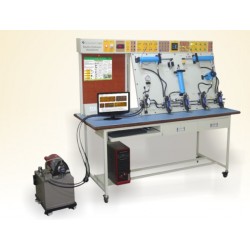
The training board-simulator is a great educational tool that allows students to learn the structure of CAN gateway system, study its components, and perform various measurements, tests and other diagnostic procedures.
Fully functional CAN – BUS network system is installed in a mobile aluminum frame. This CAN BUS training board is specially designed to help technical students understand the system`s construction.
The educational training board is based on OEM components of Mercedes – Benz. The stand is equipped with a functional CAN GATEWAY 2.0 system.
Oscilloscope/multimeter
- System’s parameters are measured by connecting to the banana connector
- Ability to measure electrical signal parameters of system component
Control unit diagnosis
- Diagnosis through OBD 16 – pin diagnostic connector
- Diagnose all presented control units in the CAN bus network by using an automatic search (depending on the diagnostic tool possibilities)
- Diagnose of each control module separately
- Electronic control unit (ECU) identification
- Reading/erasing fault codes
- Displaying the operating system parameters (live data)
- Activating the actuators (depends on the control unit)
- Control unit encoding/configuration (depends on the control unit)
- 12 V battery
- 220/12 V Power supply unit
- Automotive oscilloscope
- CAN Network analyzer
- OBD diagnostic scan tool
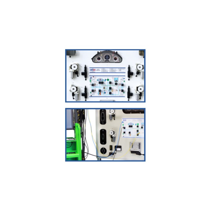
The training board is equipped with a CAN gateway 2.0 network system that includes:
– Dashboard
– Engine ECU
– Smart Key, ignition module, lock module
– SRS Airbag ECU
– Central CAN Gateway module (ECU)
– Front and rear doors control modules
– Front and rear windows lifting motors
– Front and rear windows lifting switches
• Fully functional CAN BUS network system is installed in a mobile aluminum frame.
• Educational training board is based on OEM components.
• Training board is equipped with a functional CAN BUS network system that includes: dashboard, engine ECU, smart key, ignition module, central CAN module, front and rear doors control modules and etc.
• All the components are connected to the internal network. The network is shown as a diagram for better understanding.
• The communication modules could be connected or disconnected by banana plug jumpers. There could be a possibility to disconnect Low and High speed CAN lines in the stand.
• CAN BUS diagram with built – in banana plug jumpers for measurements and simulation of system malfunctions.
• Possibility to simulate more than 10 system faults.
• The window lifting motors are active and controlled by switches and doors control modules through CAN gateway network of the car.
• The stand has a closed structure – internal wiring is not visible.
• Power supply: 12 V
• Dimensions (H x L x W): 1850 x 1380 x 600 mm
• Weight (netto) approx: 60 kg
• CE certificate


