Shopping Cart


")
")
")
")
")


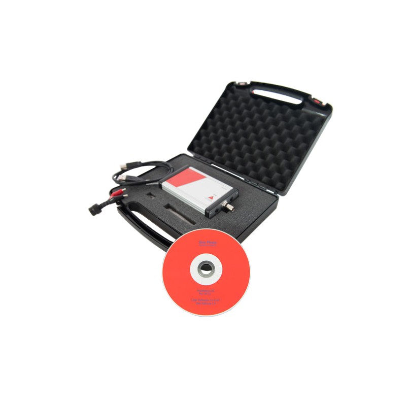
Model AO-16777k is the most widely used device of the product family for LCR and Impedance Measurements up to 16.777 MHz.
The LCR impedance analyzer / meter are designed for measurements up to 16777 MHz (~ 17 kHz).
The Model AO-16777k can be used for measurements between 1 kHz and 16777 kHz.
They can be operated directly from any standard laptop or PC without the need for an additional battery power pack or main supply.
The concept of USB power and control not only makes the instrument the smallest and most mobile of its kind, it also has fully integrated PC control and data acquisition as the standard mode of operation.
- Operability:
SinePhase measurement software or API
- Measurement points:
No limitation
- Power supply:
5V / 400 mA (via USB, no extra supply required)
- Dimensions:
126 mm × 81 mm × 32 mm
- Weight:
0.2 kg
- PC protection:
Galvanically isolated USB connection
|
Power consumption |
5 VDC; 400mA |
|
Power source |
USB port |
|
Control interface |
USB port |
|
Built-in protection |
USB interface galvanically isolated (1000 VDC /1min, 3000 VDC /1sec) |
|
Weight |
0.2 kg |
|
Dimensions |
32 x 81 x 126 mm (without connectors) |
|
Operating condition |
-15 to +65 °C / 0 to 150 °F at < 80% humidity, non condensing (extended range on request) |
|
Electromagnetic compliance |
emitted radiation: EN 55011, class B (stringest class) immunity against discharge: EN 61000-4-2, criterion A (highest immunity) immunity against EM fields: EN 61000-4-3, criterion A (highest immunity) |
|
Terminal type |
BNC |
|
Output signal amplitude |
measurement on: max. 316 mVp max. 9,6 mAp measurement off: no signal |
|
Output impedance |
measurement on: 33 Ohm measurement off: 330 kOhm |
|
Discharge energy absorption |
max. 1 millijoule |
|
Probe calibration function |
to compensate individual probes against series and parallel R, parallel C, series R, series L |
|
Frequency range |
1kHz to 16.777 MHz |
|
Frequency sweep stepwidth |
1Hz to 250kHz; |
|
Frequency resolution |
1 Hz |
|
Absolute frequency error |
typ. +/- 0,001% |
|
Impedance values |
versus frequency: ΙZΙ (Impedance Magnitude), φ (Phase), R (Resistance), X (Reactance) dual plots: ΙZΙ and φ vs.Frequency, R and X vs.Frequency complex plot: X versus R (Nyquist Diagram) |
|
Admittance values |
versus frequency: ΙYΙ (Admittance Magnitude), φ (Phase), G (Conductance), B (Susceptance) dual plots: ΙYΙ and φ vs.Frequency, G and Β vs.Frequency complex plot: B versus G (Nyquist Diagram) |
|
Capacitance |
Capacitance vs. Frequency |
|
Inductance |
Inductance vs. Frequency |
|
Scaling options |
full-scale automatically or manually settable; linear or logarithmic display option for both axis |
|
Save/load options |
- save/load measurement as data |
|
Printing options |
- graph only - full panel |
|
Data export options |
- text file format(*.txt) |
|
Minimum PC/Laptop† requirements |
- 1 GHz clock rate |
|
Operating system † |
Microsoft Windows 2000, 2003, ME, XP, Vista, or Windows 7 (other on request) |
† not included
|
Impedance values |
10mΩ to 100kΩ |
|
Admittance values |
10μS to100S |
|
Capacitance |
0.1 pF to 10 mF |
|
Inductance |
0.1nH to 10H |
|
Phase |
+90 to -90 degree; +π/2 to -π/2 |
|
Standard operation |
approx. 30 msec per frequency step |
|
With noise reduction |
approx. 60 msec per frequency step |
|
Additional optional delay time |
settable from 3 msec to 300 msec / frequency step (for high-Q measurements) |
|
Impedance values |
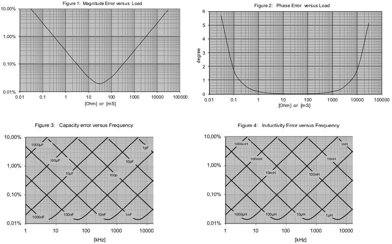
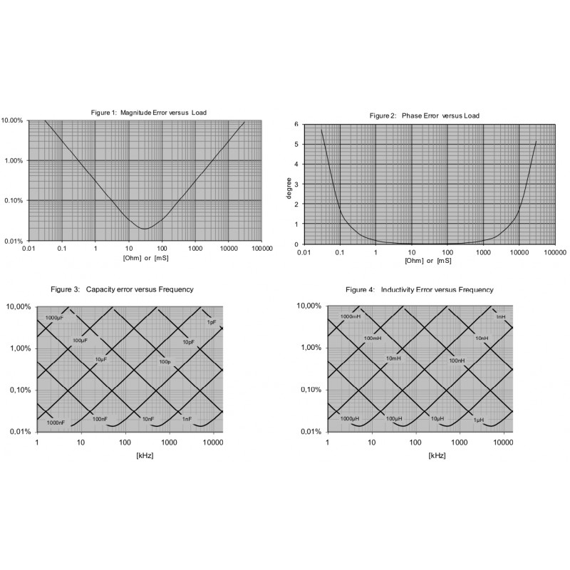
typical full frequency range error (shortened probe): +/-10 mΩ typical single frequency repetitive error (shortened probe): +/- 1 mΩ typical 100 kHz BW error (%), full Z range: (3mΩ/Z + Z/300kΩ•100% (see Fig.1) |
|
Admittance values |
typical full frequency range error (20 mS): 0.05 % typical full frequency range error (open probe): +/-10 μS typical single frequency repetitive error (open probe): +/- 1 μS typical 100 kHz BW error (%), full Y range: (3μS/Y + Y/300S•100% (see Fig.1) |
|
Phase |
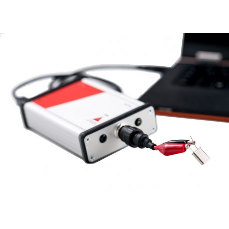
see Figure 2 |
|
Capacitance |
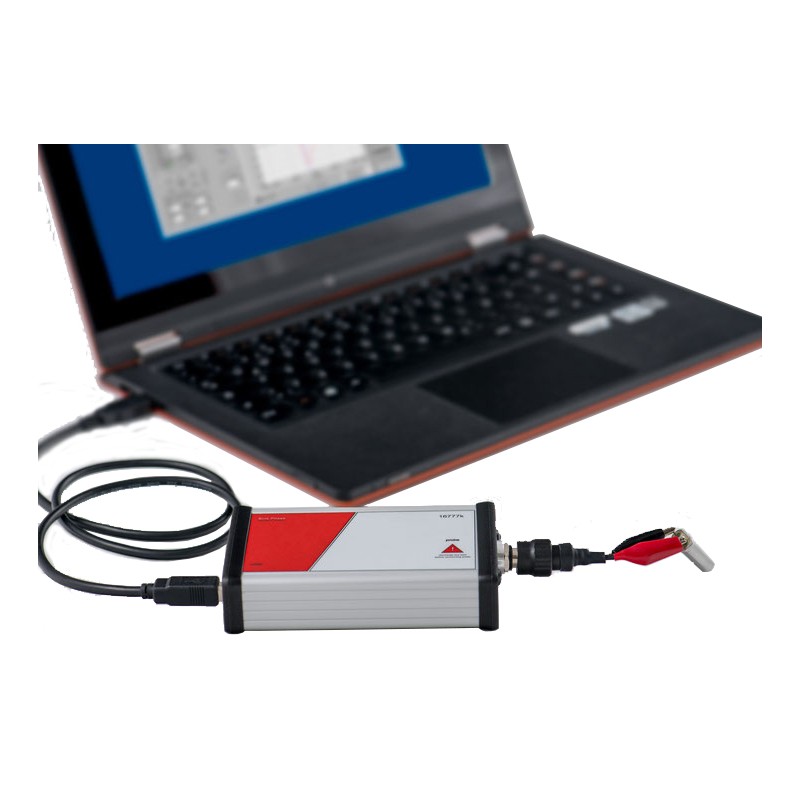
see Figure 3 |
|
Inductance |
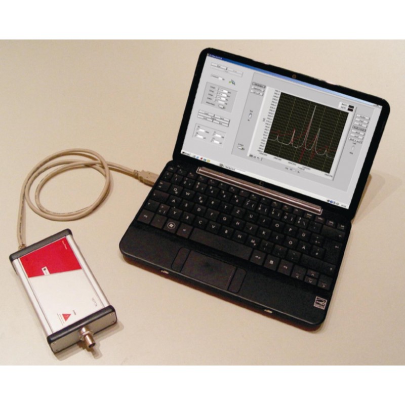
see Figure 4 |


