- Home
- Who We Are
- Products
-
Brands
-
Products by Measure
- Vibration Analyzers
- Peristaltic Pumps
- Airflow
- CO Carbon Monoxide
- Geiger counters
- Destiladores
- Spectrophotometry
- Sterilization
- Fluorescence
- GEOTECHNICS
- Soil Moisture
- Leaf area index
- Rain Gauge
- Meteorology
- Water Level
- O2 Oxygen
- pH
- Differential Pressure
- Radiation
- Salinity/Conductivity
- Telemetry
- Air Speed
- Relative Humidity
- Veterinary
- FUEL CELL HARDWARE
- Network Analyzers
- Calibrators
- WATER FLOW
- Color / Colorimeter
- Particle Counters
- Wind Direction
- Spectrometry
- Evapotranspiration
- Photosynthesis
- Cracks in Buildings
- Pipes Inspection
- Quantum Light
- Movement & GPS
- Diesel Level
- Oxígeno Disuelto DO
- Atmospheric Pressure
- Radon
- Sap/Sap Flow
- Temperature
- AIR QUALITY
- Ammonia
- Chlorophyll
- Conductivity in Soil
- Dendrometers
- Electrochemistry
- Spectroradiometry
- Pharmacy & Medicine
- GAS (ANALYZERS)
- Leaf Wetness
- Idc (DC Current)
- KW & KW/H
- PAR Light
- Nitrate
- Occupation and Time
- Particle Meters
- Soil Water Potential
- Pulses
- Flavor/Taste/Acidity
- Sodium
- Turbidity
- VOC
VG-DISPLAY UNIVERSAL SENSOR DISPLAY
Universal Sensor Display Includes:
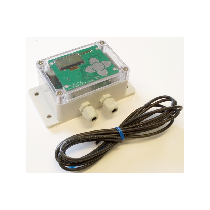
Circuit board, water tight box, power cable, and cable glands. Buy sensors separately.
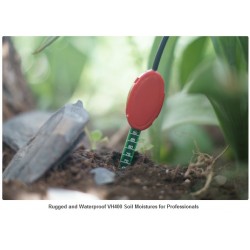
Our Universal Sensor Display provides a convenient and easy way to visually display sensor data. It is capable of reading all Vegetronix brand analog sensors as well as many analog sensors from other manufacturers.
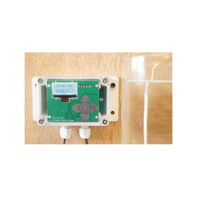
The Universal Sensor Display features a back-lit graphical LCD and touch button interface, all in an easy to mount, rugged, water-tight enclosure. The Sensor Display uses water tight cable glands for cable exits. The touch screen is responsive and is protected by the transparent enclosure cover.
Using the menu screen, you select the sensor type that you want to read, or you can configure the display to be a voltage meter, event counter, or frequency counter. The measurement units are configurable, and are available in metric or English units. The sample rate, and sensor power on time are configurable. The input readings can be calibrated with an offset, and scaling factor, so that you can fine tune sensor calibration, and accommodate nearly any linear analog sensor.
Our design minimizes power usage. In sleep mode the unit consumes only 60uA. The sensor power is only turned on before taking a measurement, and then the display goes back to sleep, until a new sample needs to be taken. The backlight can be configured such that it is on only briefly when the keypad is in use, or constantly on, if power usage is not a concern.
Universal Sensor Display Specifications
| Sensor Display | |
| Power consumption (Sleep Mode) | 60uA |
| Power consumption (Back Light) | 20 mA |
| Maximum Sensor Input Voltage | 0V to 3.5 VDC. |
| Supply Voltage | 3.5V to 20 VDC. |
| Frequency Counter Range | 1 to 22MHz |
| Dimensions | See drawing below. |
| Sample bits | 10 bit |
| Input Impedance | 1M ohms |
| Operational Temperature | -40C to 85° |
Universal Sensor DisplayWiring Table
| Terminal Block TB1 | ||
| Pin 1 | Red | POWER IN: 3.5V to 24 VDC. (This voltage will be passed to the sensor, so make sure it does not exceed the specifications of your sensor. ) |
| Pin 2 | Black | POWER GROUND |
| Pin 3 | Red | SENSOR POWER |
| Pin 4 | Black | SENSOR INPUT: (0 to 3.3V max) |
| Pin 5 | Bare | SENSOR GROUND |
Universal Sensor Display Drawing
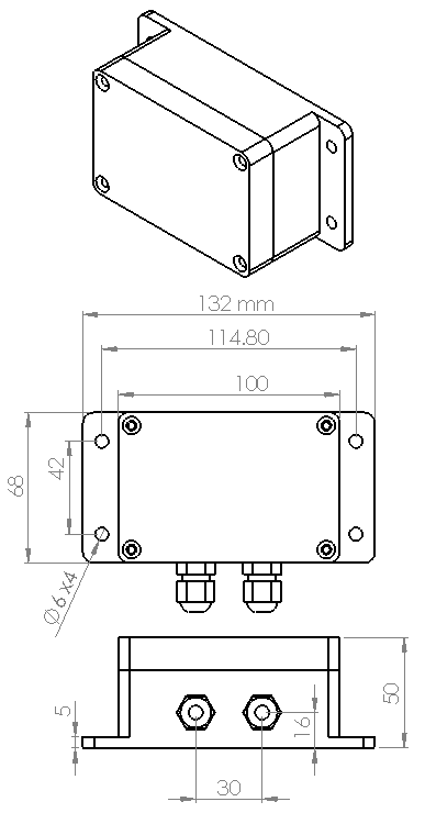
Sensor Display Enclosure Drawing
Universal Display Menu
The display menu is accessed by pressing the center key on the keypad. You can use the left button to exit the current menu, and to go back to the previous menu. When setting values use the center key to enter and save the value. If you use the left key without pressing the center button, the values will not be saved.
- Data Display - use the right button to switch between the numerical and graphical display.
- Menu
- Sensor Type- Select the type of sensor
- Voltage - This reads the voltage of the sensor.
- VH400 - This reads the voltage from a VH400 moisture sensor and displays it as a VWC (Volumetric Water Content) percentage.
- THERM200 - This reads the voltage from a THERM200 temperature sensor and displays it in degrees Fahrenheit or Celcius.
- AquaPlumb - This reads the voltage from an AquaPlumb water level sensor and displays it in the AquaPlumb units you have selected.
- Frequency - This reads a digital frequency (0 to 3V) and displays it in Hz.
- Counter - This reads a digital pulse count (0 to 3V) and increments and displays the count every time it detects a raising edge of a pulse.
- Sleep Delay - This determins how long the display stays on, until it goes into sleep mode. If you want the display to remain on always, then set this value to 0. This is not recommended because it it will consume much more power.
- Sample Delay - This is the sample period, or time between samples. The actual sample period is this time plus the sensor warm up time.
- Warmup Time - Set this time to the amount of time in miliseconds that it takes for a sensor to warm up and settle. Set this time to zero, if you want the sensor to be constantly powered, and never turn off. Setting the value to zero is not recommend for normal operation, as it will consume much more power. While calibrating an AquaPlumb sensor, set this to zero, and then return it to a non-zero value afterwards, to conserve power.
- Offset Cal - This is normally set to 1 for voltage sensors. You set this value to scale the read voltage. You will need to set this value for aquaplumb sensors to convert a voltage into a distance or volume. This setting is useful for scaling aquaplumb units to the desired level.
- Scale Cal - This is normally set to 0 for most sensors. If your sensor has an offset error, you can use this value to compensate.
- Back light - This turns on or off the backlight. Turn off the backlight to conserve power.
- Temp Units - This sets the temperature units for the THERM200 sensor to either °C or °F.
- Aplumb Units - This sets the units of the Aquaplumb Sensor.
- mm
- cm
- m
- in
- ft
- cc
- ml
- l
- oz
- gal