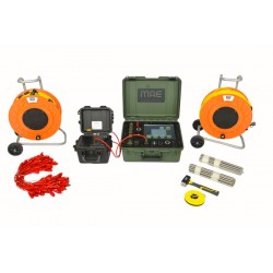
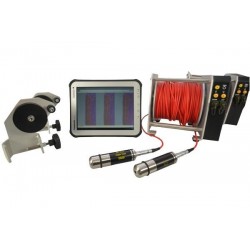
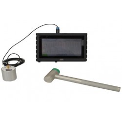
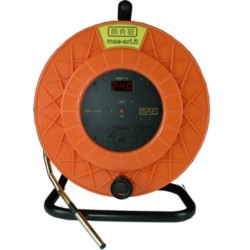
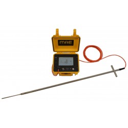
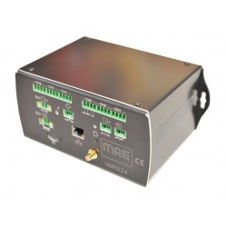
MAE ET300 Multichannel Georesistivimeter 24-48 Channels

ET300

MAE srl

New

STRENGTHS:
Parallelization of measurements for pole-dipole, pole-pole, dipole-dipole and three-dimensional configurations

24-bit resolution

Pseudosection in real time

Allows VES and tomography surveys.

Add to wishlist

Type of Instrument Georesistivimeter


Advantages of the MAE ET300 data acquisition architecture:


- Dramatically reduce the time it takes to complete a survey.

- Possibility of tackling investigations that were previously unthinkable, due to the high number of measures required

- Possibility of repeating the measurements several times to minimize the uncertainty, for the same time taken

- Lower energy consumption

- Recording of the standard deviation for each measurement

- Graphical representation with error bars of the measuring points

- Real-time visualization of the pseudo-section of resistivity

- Availability of an automatic repetition function of the measurements with an error percentage greater than a configurable threshold.


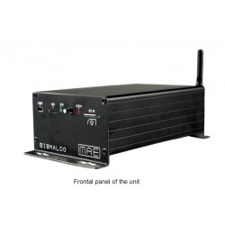
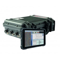
The ET300 is a new compact georesistivity meter for SEV and multi-electrode geoelectric prospecting with 24 or 48 electrodes.

The main feature of this instrumentation is the maximum versatility of use combined with the high speed of execution of surveys, both 2D and 3D. ET300 is managed via a normal laptop or tablet via USB connection.

It is equipped with the "preview" function which allows the user to visualize a preview of the pseudo-section derived from the train of data just acquired directly in the field.The use of this function allows the operator to immediately verify the logged data.

The instrumentation carries out the measurement or the measurement cycle set by the user in automatic mode.

Once the measurement cycle is concluded, the acquired data can be immediately displayed using the "preview" function, the use of which allows the operator to immediately check the recorded data and process it with the relative data processing software.

General:

ADC Technology: 24bit Delta-Sigma ADC

Number of electrodes: 24-48 (with 20 channels)

Array configurations: 1D, 2D, 3D

Measurements: Self potential, resistivity, induced polarization

Dimension: 40x33x17 cm

Weight: 6.3kg

Export compatibility: RESinv, ERTlab, ZondRES, MAE

Roll-along function: Software controlled

Real-time pseudosection: 1D, 2D and 3D

Sequence generator: 1D, 2D and 3D

Case: IP67

Enviromental condition: -20°C/90°C

Power supply: External 12V battery, suggested 100Ah

Average consumption : 0.5A, up to 50A peak
 

Output:

Power output: 300W

Output voltage: ±50V, ±100V, ±200V, ±400V, ±800V

Output current: up to 6A at 50V, up to 0.375A at 800V

Energization diagram: Custom from 250ms

Precision: ±0.2 μA

Accuracy: < 0.2 %
 

Input:

Measurements strategy: Parallel

Input voltage: ±25V

Precision: 1.5 μV vs fullscale

Accuracy: < 0.2 %

Input impedance: 2.5MΩ

Stacking and noise reduction: Up to 255

Input notch filter: 50 Hz

Self potential adjustment: Automatic

IP's windows: Up to 20 windows at 20ms interval

Multi-electrode Geoelectrical Prospecting+

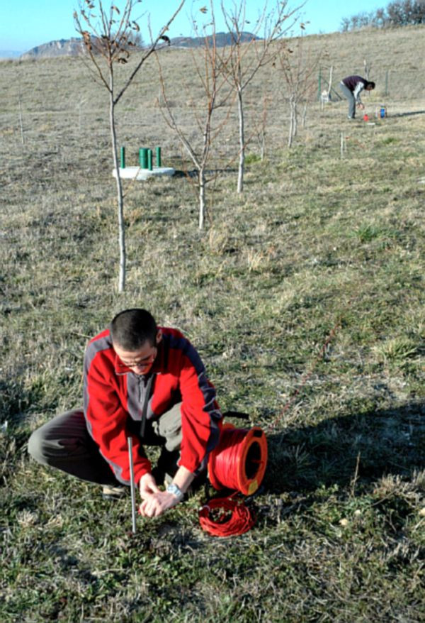
This survey method calculates ground resistivity based on voltage difference (d.d.p.) measurements. The process involves introducing an electric field into the ground using current electrodes and measuring the d.d.p. at separate measurement electrodes. Using Ohm's second law, the resistivity value is determined, reflecting the intrinsic properties of the material. Since rocks are naturally resistive, variations in resistivity are primarily due to the presence of water in varying amounts.

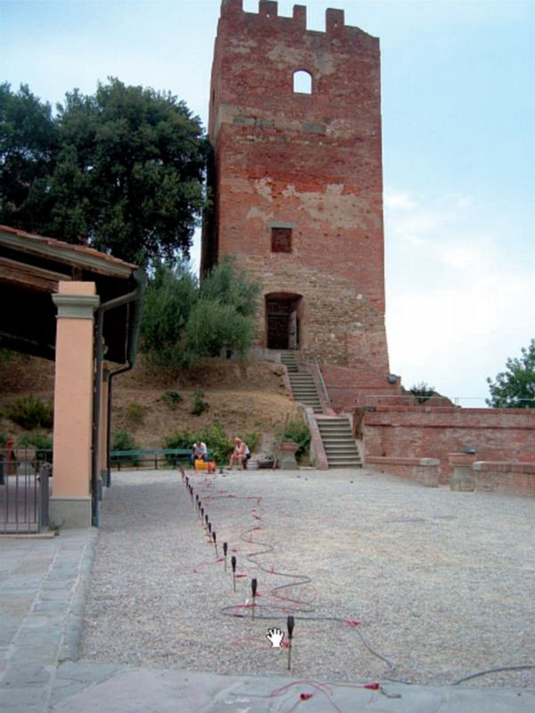
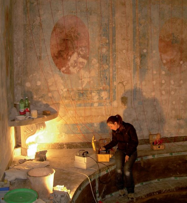
In 2D-3D electrical tomography, electrode grids (16, 32, 64, 128, etc.) are fixed into the ground at regular intervals. These electrodes are connected to commutation boxes that automatically select the measuring and current electrodes, performing all possible combinations. The system generates numerous measurements based on the number of electrodes and the geometric configuration used. The tomographic inversion of this data produces a 2D or 3D reconstruction of the ground, allowing the identification of anomalies such as cavities, water bodies, and their shapes, sizes, and spatial distribution.

V.E.S. Vertical Electrical Survey+
This survey method aims to reconstruct a 1D electro-tomography at a specific measurement point. It involves the geo-electric technique, which experimentally determines the resistivity distribution that defines the electrical structure of a medium. In the SEV method, the distance between electrodes is gradually increased while measuring the ratio between voltage difference (d.d.p.) and current intensity. The resistivity values obtained are influenced by the properties of materials at greater depths, necessitating geometric corrections. This involves introducing factors dependent on the distances between the measurement electrodes (MN) and the input electrodes (AB). Depending on electrode positioning within the geo-electric field, different quadrupole systems, such as Wenner and Schlumberger, are used. The result is a 1D profile of ground resistivity at a specific location.

Induced Polarization Measurement+

Induced Polarization (IP) is an electrical phenomenon that occurs within material media. In the time domain, it is observed as chargeability, which happens when stress is released after the interruption of a step-type electric current. In the frequency domain, it involves the dispersion of electrical resistivity as the frequency of an alternating current changes. IP sources are primarily linked to redox processes at the interfaces between metal grains and interstitial fluids (electrode polarization). Another significant IP source is the accumulation of ions in moving electrolytes due to variations in mobility along the path (electro-kinetic polarization).

Through tomographic inversion of surface data, the resulting images reflect chargeability, enabling the identification of areas with potential hydrocarbon accumulations or other significant concentrations. Chargeability is directly proportional to the amount of charge stored by the lithotype, indicating the concentration of conductive materials in the multi-electrode area.

Spontaneous Potential Measurement+

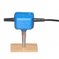
The Spontaneous Potential (SP) method involves measuring potential differences on the surface that are associated with natural electric fields, which are linked to the underground flow of aqueous electrolytic solutions in porous media. By analyzing SP anomalies on the surface, the intensity and position of ionic charge concentrations of both polarities can be determined.

The test involves placing two electrodes: one near the measurement station and the other moved along subsequent stations on the line. Alternatively, both electrodes can be moved while maintaining a consistent interval between them, mapping the ground based on spontaneous potential variations. This method is particularly useful in mining for locating sulfides and graphite, as well as in archaeology. Underground water flows can be influenced by archaeological structures, which may act as drains or obstacles. By identifying SP anomalies, it is possible to indirectly detect these underground structures.

30 other products in the same category: